
Featured Post

Assembly methods in Solidworks Design

Assembly is the process of combining or assembling several parts in a certain relationship. An assembly is a combination of two or more parts, also called components, in one SOLIDWORKS document. We can position and orient components using pairs that form connections between components. Very easy process. There are 2 assembly methods in Solidworks: 1. Part coordinate system method. 2. Part Method Part coordinate system method Click the new icon and part icon to create a new image. 2Click and create a part image. Then save and name the file part1. Create a new part and then create a new plane that is 30 mm apart. Then save and name the file part 2. After the above process is complete, we enter the stage for assembling part 1 and part 2. Here are the steps: Click the New icon and click the assembly icon. In the menu bar select windows, tile horizontally. So a horizontal tile window will appear Click the 2D Sketch icon so that origin will be active in windows assembly. Click on the text pa...

Solidworks 3d Extrude Cut Tutorial

Extruding 3D object provides you with Solidwork.
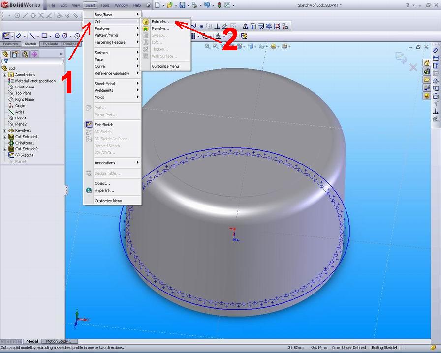
we can make Extruded Cut by performing the steps:

Make sketches.
Click Extruded Cut feature on the toolbar, or click Insert,
click Cut,
click Extrude

Click OK
Extrude cut is a feature that removes material from a part or assembly.
With the parts of multibody, we can use the deduction to make disjoint parts.we can control the other parts to keep and which parts are affected by the cut-Extrude.


Comments

Popular posts from this blog

Right click menu in solidworks customize

In a SOLIDWORKS document, click Tools > Customize, or right-click in the window border and select Customize. Select a menu. Select the command to add, rename, or remove. Displays the code name of the selected menu. Right-click in the Graphics window on a model, or in the FeatureManager on a feature or sketch to display the Context-sensitive toolbar. If you are in the middle of a command, this toolbar displays a list of options specifically related to that command. Right-click an empty space in the Graphics window of a part or assembly, and a selection context toolbar above the shortcut menu is displayed. This provides easy access to the most commonly used selection tools.

Assembly methods in Solidworks Design

Assembly is the process of combining or assembling several parts in a certain relationship. An assembly is a combination of two or more parts, also called components, in one SOLIDWORKS document. We can position and orient components using pairs that form connections between components. Very easy process. There are 2 assembly methods in Solidworks: 1. Part coordinate system method. 2. Part Method Part coordinate system method Click the new icon and part icon to create a new image. 2Click and create a part image. Then save and name the file part1. Create a new part and then create a new plane that is 30 mm apart. Then save and name the file part 2. After the above process is complete, we enter the stage for assembling part 1 and part 2. Here are the steps: Click the New icon and click the assembly icon. In the menu bar select windows, tile horizontally. So a horizontal tile window will appear Click the 2D Sketch icon so that origin will be active in windows assembly. Click on the text pa...

Drawing Template and Sheet Format

Project 1 – Drawing Template and Sheet Format  Project Objective Create a C-size Drawing Template.  Create an A-size Drawing Template.  Project Situation As the designer, your responsibilities include developing drawings that adhere to the ASME Y14 American National Standard for Engineering Drawing and Related Documentation Practices.  The foundation for a SolidWorks drawing is the Drawing Template.  Drawing size, drawing standards, units and other properties are defined in the Drawing Template.  Sheet Formats contain the following: border, title block, revision block, company name, logo, SolidWorks Properties and Custom Properties. You are under time constraints to complete the project on schedule.  Create a SolidWorks custom Sheet Format.  Import an existing AutoCAD C-size drawing.  Create a custom C-size Drawing Template and an A-size Drawing Template.     fr: SDC PUBLICATIONS Schroff Development Corporation www.schr...